So I decided to rebuild it.
Parts:
- A new carb - VM26 - $26
- New wiring harness $50 - there are many to choose from and based on the looks, I ordered WonVon Complete Electric Stator Engine Wiring Harness THIS COMES WITH NO DIRECTIONS! - details below
- New front break cable - $11
This was a one for one swap. It fit perfectly. The only difference is the choke assembly. This has a handle that clicks, where I just have a choke cable to adjust on the old version. I think I can just swap out the assembly and be good to go. I find that if I take off the seat, it is very easy to adjust the choke.
Wiring Harness:
 The harness came with no connection diagram or instructions and was a bit differen. It also had some different connectors for the lights and Stator. Was planning on just reconnecting the old Stator but since the connections were different, decided to change that out. Details on Stator replacement below. Here is a diagram I made based on my current connections. For the lights, I reused the light connectors from the old harness and connected the blue, white and green wires in the front of the new harness.
Replacing the Stator:
 This was not an easy task and took me a few hours. I could not find any good instructions so mostly figured this out from looking at many other types of replacement.
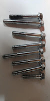
Step 1 - Remove the Eight bolts around the Stator compartment. Starting with the top center bolt and working counter clockwise (to the left), remove the bolts. There are different sizes so keep them in order. And then repeat from the top when putting them back in. You may have to remove you stand and gear shift as well.
Step 2: On the same side - remove the three bolts on the starter casing. Remove the casing - be careful to note the gear, it may fall out. The larger gear is on top or the closest to the outside.
Step 3 - Remove the one bolt on the top left in the starter casing where the gear sticks through. On the other side of the ATV, remove the long screw bolts holding the starter to the casing from the .
Step 4 - Using a small tack hammer - lightly tap on the Stator housing to dislodge it and break the seal. You maybe able to just pull it off without tapping, but mine was stuck on there.
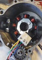
 Step 5 - Remove the old Stator. Cut the cable - remove the three bolts on the Stator. Remove the two screws holding in the pulse sensor. This was difficult as they would not come out and I was afraid of stripping the Philips screws. I soaked them in bolt release lubricant for several hours. I eventually had to heat the outside of the casing with a torch before they would break free. Use anti-seize compound on the bolts before putting them back in.
 Step 6 - Install new Stator - Note the color and the position of the wires to the connector. I marked them with a Sharpe.
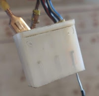
Using a small paper clip or piece of hard wire, slide it up in to the connector to push the slide pin down. This will release the pin, and allow you to remove the wire from the connector. After all the wires are removed from the connector, slide the wires from the inside of the case out through the cable hole. Re-seat the runner grommet and the three bolts to the Stator, Put the anti-seize compound on the pulse sensor bolts and install them. Reset the wires back in to the connector as noted.
Re-install the casing in the reverse order. Pay special attention to how the wires are routed up from the engine. Not getting them tucked in good and hidden will prevent the casing covers from aligning correctly.
Still no Start????
After all this and getting the harness connected and all the parts installed, the bike still would not start. I did not have a spark - why????? There are two gotchas here!
1) Mid way in the harness, you will find two wires that have matching barrel connectors, join them as this connects 12 volts to your switch. See the wiring diagram.
2) The kill switch on the new multi-switch is a slider. To kill the engine, you slide the switch to either side. However, this is a locking slide, you must push in the button to release the kill. After several hours of trouble shooting this and finding this video on how to diagnose the Stator and CDI, I figured this out. It came down to the one pin on the CDI being grounded so know that was shorted some where. I took the harness apart and found the joined wire going back to the multi-switch and by accident, pushed the button in and noticed the change in ohms on the CDI. After that - started right up!
Connecting the Lights:
Since the connectors on the front are different. I used the old light connectors and soldered them to the Blue/White connector, and then use the green wire for ground. Most the other wires on the front or spare connectors as noted in the diagram. I think some could be used for the back break light that I do not have connected - but the running light works.
Hope this helps someone else - and happy trails!
tim


